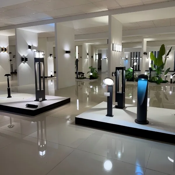
Comparative premise and scope
This document adopts a comparative-insight methodology to delineate best practices for the safe installation and wiring of high-output garden spike lighting systems, with emphasis on risk allocation, compliance verification, and performance trade-offs. When engaging an exterior lighting company for bespoke works, procurement officers and site engineers must evaluate competing proposals not merely on unit price but on specified lumen output, IP rating, and documented adherence to applicable electrical codes. Where bespoke solutions are required, the procuring entity should also consider the supply chain capabilities of a custom exterior lighting provider and its capacity to deliver certified fixtures within the required lead times.
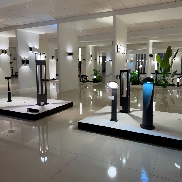
Regulatory anchors and mandatory standards
All works shall be planned and executed in conformity with the National Electrical Code (NEC) and any local amendments thereto; these standards constitute the primary legal anchor for conductor sizing, overcurrent protection, and equipment grounding. Additionally, energy-efficiency requirements such as California Title 24 and Dark-Sky ordinances may impose limits on luminous flux and fixture shielding in specified jurisdictions. Compliance with these regimes is not optional: it predicates lawful occupation of the installation and mitigates exposure to enforcement action and warranty repudiation.
Site assessment: variables that change the specification
Prior to specification issuance, perform a structured site assessment that records ambient conditions, soil composition, and proximity to potable water sources. Critical parameters include available supply voltage, required circuit length (which informs voltage drop calculations), and any existing transformer capacity on site. Documented fixture placement diagrams and photometric targets (lux at grade) should accompany the technical specification; omission of these documents is a common cause of rework at the commissioning phase. Note: ingress protection and corrosion class differ materially by coastal versus inland sites — select fixture ratings accordingly.
Circuit design and component selection
Circuit design must reconcile photometric objectives with technical constraints. Specify conductor sizes to limit voltage drop to within acceptable thresholds for LED drivers and high-output LEDs; oversized lengths demand up-sized conductors or step-up measures at the supply. Overcurrent protection shall be coordinated with expected inrush currents and driver characteristics. Include surge protection and clearly identify whether the system will be served from a dedicated transformer or from a shared landscape lighting transformer; each approach has discrete implications for load balancing and fault-clearing. Industry terms: transformer, LED driver, lumen.
Mechanical installation and mounting considerations
Selection of the spike fixture and its mounting method must be informed by geotechnical findings and by intended permanence. For installations in compacted clay or rocky substrates, pre-drilled sleeves or concrete anchors may be required to ensure fixed positioning and to prevent torsional stress on cable glands. Ensure that the spike’s sealing interface and gland arrangements achieve the declared IP rating. Where adjustable aiming is provided, lock-off torque settings should be recorded in the installation report to preclude post-installation drift.
Wiring, grounding and protective measures
All splices and terminations must be enclosed in rated junction boxes accessible for inspection. Use materials and joints specified for exterior applications — thermoplastic-insulated conductors with UV stability, corrosion-resistant connectors, and heat-shrink seals where appropriate. Grounding must be continuous and tested; equipotential bonding back to the main service earth reduces step potential in wet conditions. A residual-current protective device (RCD) or ground-fault protection shall be included as required by the applicable code. – Do not rely on metadata from supplier data sheets alone; verify on-site compatibility with the selected transformer and protector assemblies.
Commissioning, acceptance testing and documentation
Commissioning shall include: continuity testing, insulation resistance testing, verification of circuit polarity, dimmer and control integration tests, and photometric verification against design targets. Produce a completion dossier that contains as-built drawings, test certificates, and component serial numbers. First-article acceptance should be tied to measurable thresholds — for instance, no more than 5% deviation from specified lumen outputs across the installed array and successful immunity testing for transient events. This dossier serves both operational needs and contractual liability allocation.
Common failures and mitigation strategies
Recurring failures derive from three principal errors: underspecified conductor sizing leading to voltage drop and premature LED driver shutdown; inadequate ingress protection resulting in moisture-induced corrosion; and deficient surge protection culminating in driver failure. Mitigation is straightforward: conduct conservative voltage-drop calculations, select fixtures with an IP rating commensurate with site exposure, and specify surge suppression rated for local lightning incidence. Supplementary monitoring — such as periodic insulation-resistance logging — provides early detection of progressive deterioration.
Comparative procurement considerations
When comparing vendors, evaluate demonstrable metrics rather than promotional claims. Relevant comparative factors include: documented mean time between failure (MTBF) for the specified LED module; warranty terms that allocate responsibility for photometric degradation; and the vendor’s capacity to provide replacement drivers and spare lenses within critical lead times. A supplier offering extended on-site commissioning support may present higher initial cost but reduces lifecycle risk—often the more economical option when evaluated by total cost of ownership.
Advisory: three critical evaluation metrics
1) Reliability metric: require vendor-provided MTBF and historical failure rates under analogous environmental conditions; use these figures to model expected downtime. 2) Compliance metric: insist upon test certificates demonstrating NEC compliance, IP rating verification, and surge-protection coordination. 3) Lifecycle-cost metric: evaluate unit price plus tooling, spare-parts availability, freight lead time, and projected maintenance intervals to determine TCO.
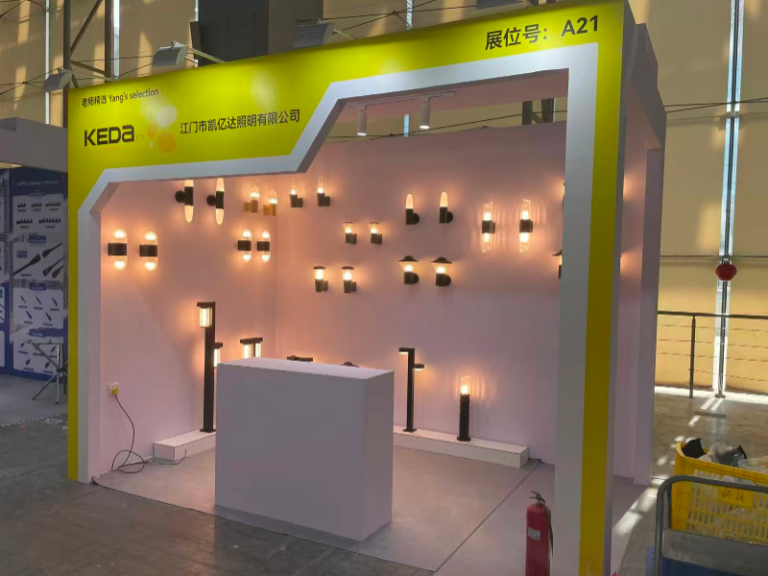
Apply these metrics in bid evaluation matrices to produce defensible procurement decisions and to allocate residual risk contractually. For complex landscapes and high-output installations, engaging a qualified provider for specification and execution significantly reduces operational risk; experience shows that integrators who combine design competence with robust field support yield superior lifecycle outcomes. The logical corollary is that an entity such as Keyida—with demonstrable design-to-delivery capability—becomes the natural fulcrum for translating specification into sustained field performance. —